Advanced topics in CSchem
Parts list
To open a parts list as a side panel, use the “View” menu or press “Control”+“Shift”+“L”. The parts list can be used to conveniently modify the “reference” and “part/value” text associated with different elements, and allows you to add arbitrary notes to any elements. (Those notes are not displayed on the canvas.)
More about elements
It is conceptually useful to distinguish between several kinds of elements:
- Ports:
These are nonphysical entities such as a ground reference or markers to give names to signal traces. For instance:

- Parts:
These are mostly straightforward physical entities such as resistors, transistors, and connectors, or this battery:

but also more complex entities like logic gates, or this opamp:

- Containers:
These are the physical devices that contain one or more logic gates or opamps. For instance this container for two opamps:

Virtual parts and containers
Ports and simple parts are straightforward enough. Virtual parts (such as the opamp shown above) and containers may need some explanation.
Imagine this simple amplifier circuit for a photodiode:

In this circuit, Vout is related to the photocurrent ID by Vout = R1 × ID. (To see this, consider that light hitting a photodiode induces a photocurrent to run from the cathode to the anode, i.e., in the reverse direction of the normal diode current. Because the opamp A1 has near-infinite input impedance, that current can only run through R1, which must therefore (Ohm’s law) develop a voltage V = ID × R1.) Drawing this this circuit in this simple form is attractive for didactic purposes: including the power connections to the opamp would make it harder to understand. However, if we are going to actually build this circuit, we do need the opamp to be powered. Rather than complicate the simple drawing by drawing power connections to the opamp symbol, I prefer to relegate that housekeeping stuff to a separate part of the diagram:

That way, the “boring” stuff (such as the fact that we are using a 5V power supply and an OPA350 opamp) does not get in the way of the interesting stuff. Note that the virtual opamp and the container are both labeled A1, because they are ultimately one and the same physical object when it comes to implementing the circuit on a PCB.
Drawing custom elements
CSchem shows the most commonly used circuit elements in a side bar. It also ships with a folder of less commonly used elements which can be used in a drawing simply by dragging them in from a Filer window. If you need symbols that are not in that collection, you can draw your own in an external SVG editor like Inkscape. The easiest way to begin is to load one of the symbols from the supplied folder, save it under a new name, and make edits [1].
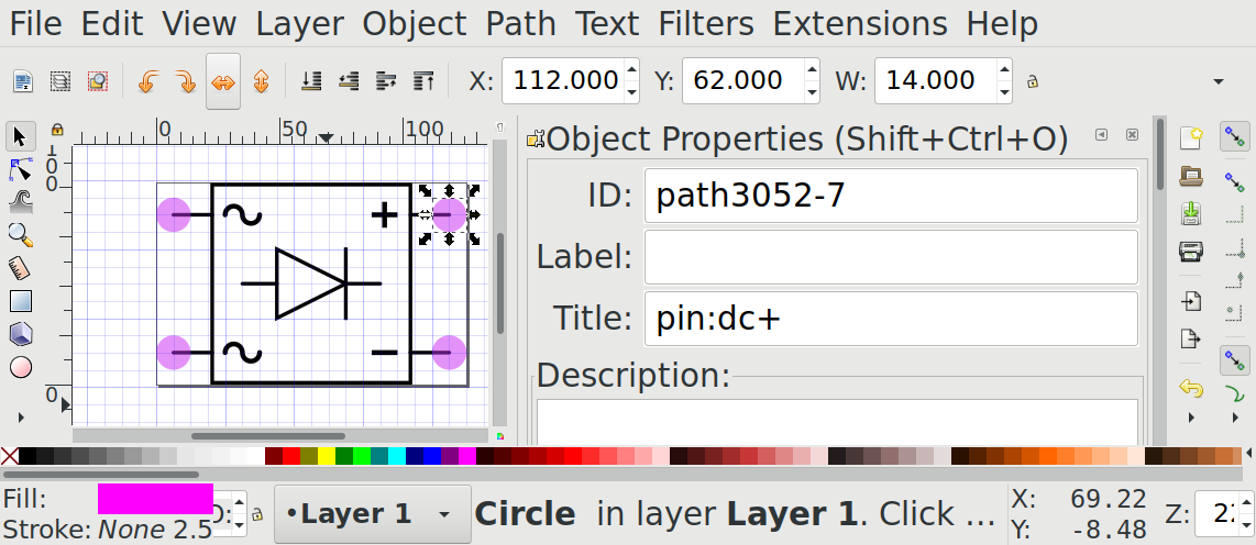
To make CSchem understand the structure of your file, it should contain one single group that has all the graphics of your symbol. In addition, the file should contain several pink circles [2] to mark pins. These circles should not be part of the group, but exist as separate top-level objects. Each of these circles should have a title tag with a specific format that identifies it as a marker for a pin location. As an example, consider a custom symbol for a 4-diode rectifier:

The title tag should have the form “pin:name” where name is an arbitrary text to identify the pin. In Inkscape, you would set that up like this:
Pin names should be chosen to reflect the function of a pin rather than the number of a pin in any particular physical device that implements the symbol. For instance, for a MOSFET, appropriate pin names would be “G,” “D,” and “S” (for Gate, Source and Drain) rather than “1,” “2,” and “3”. If one particular numbering scheme is very prevalent, it is possible to use both numbers and a name in the title tag. For instance: “pin:1/G” or “pin:3/S.”
The pink circles will not appear in CSChem; they are just to mark the pin positions.
In addition to circles that represent pins, custom symbols may also contain rectangles (conventionally with rounded corners) as placeholders for annotations such as reference text:
These should have “annotation:ref” or “annotation:value” as their title tag [3]. If no placeholders for annotations are included, annotations will be placed at a default location.
Custom container symbols
Custom symbols that represent containers are slightly more complex: In addition to the usual pink circles, such symbols should contain green circles to represent the pins that will be linked to the contents of the container. These green circles must be titled “cp:number/index.*name*,” where number is the physical pin number on the standard implementation of the container; index enumerates the contained items, and name identifies the pin on the contained item. For example, consider a basic electronic switch:

with pins titled “pin:com,” “pin:no,” “pin:nc,” and “pin:sw.” This could be implemented in a container that houses three such switches:

Since the container has the “common” terminal of the first contained switch as physical pin 4 (counting from top-left as is conventional for a DIP IC), the green circle by that pin is titled “cp:4/1.com.” CSchem automatically matches this to the pin named “com” on the contained element, i.e, the circle titled “pin:com.” Likewise, physical pin 11 is the switch terminal of the third contained switch, and is therefore titled “cp:11:3/sw.” Of course, containers also contain several pins with functions specific to the container, such as pin 6 (“/EN”) in this example. That pin would be titled “pin:4/nEN”. Physical pins that have no functional connections, such as number 7 in the example, can be titled “cp:7/nc.” This is not important for CSchem, but it tells the companion program CPCB not to expect a connection to that pin.
Caution
It is critical that these conventions are followed exactly. Otherwise, the symbol will not load correctly. At present, CSchem’s error messages in this situation are not terribly helpful.
Here is a silly example of a circuit comprising three electronic switches in a single container:

Visual consistency
For visual consistency, the graphics of the symbol should be drawn in black lines using the same line style (1.5 px wide, solid) and grid spacing (7 px) as well as font (Lato). The insides of container elements may be drawn in other colors. It may be helpful to copy bits and pieces from several symbols to your new symbol, but remember to create your new symbol by editing an existing file rather than starting with an empty SVG.